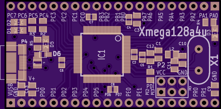
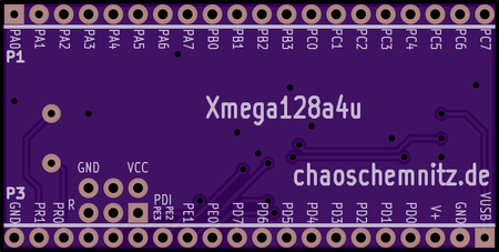
Xmega128a4u BO Testplan
Erscheinungsbild


This is the explanation how to test the Xmega128a4u breakout board in mass production process.
- All pins on the two 20-pin connectors are tested against short circuit or open connection.
- The crystal is testet by starting the crystal oscillator.
- LEDs are optically tested.
- USB connector is testet against short circuit and open connection.
- USB ESD protection is testet: BAS70 diode forward voltage, Z-diode breakdown voltage
- Reference voltage capacitors are tested.
Testboard


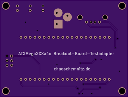
All the functions are tested by the passive testboard. "Passive" means there is no processor on the board. The testprocess is done by the Xmega Breakout Board.
Usage
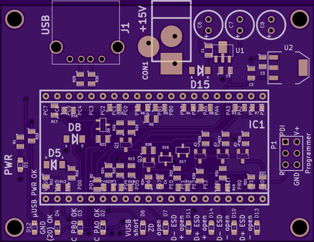
- Connect a 15 V to 30 V DC powersupply to the connector CON1. On normal operation it uses on maximum 100 mA.
- Connect the programmer to the PDI-interface P1 on the testboard.
- Connect an USB-cable to the USB-port J1 on the testboard.
- Plug the Xmega Breakout Board in the IC1 socket. (micro-USB-connector on the left side)
- Connect the micro-USB-cable to the Xmega Breakout Board.
- Download testsoftware to the controller.
- Check the LEDs.
- Unplug USB-cable and Xmega Breakout Board.
- go to 4 and plug in the next board
Indicators
- PWR-LED (D1) on the testboard must be on. Powersupply to the testboard is OK, testboard is OK, no short circuit.
With Xmega Breakout Board pluged in and testsoftware on the controller:
- green OK-LEDs
- After plugging in the USB-cable: µUSB PWR OK (D12) should light up (blinking) -- The power-pins (VUSB and GND) of the USB-connector are working correctly.
- GND (20) OK (D4) should show light. -- the second GND-pin on the Xmega Breakout Board is OK.
- C PB0 OK (D3) and C PA0 OK (D2) are blinking. -- The two capacitors for the analog reference on port b and port a are OK.
- red failure-LEDs (all red LEDs on the testboard must be off)
- VUSB short (D6) -- short circuit between VUSB and GND, maybe Z-diode on Xmega Breakout Board mounted with wrong polarity
- ZD open (D7) -- Z-diode is not connected on the Xmega Breakout Board
- ESD open-LEDs (D11, D14, D10, D13) are showing ESD-protection failures on the USB port. -- The corresponding schottky diode is not connected.
- LEDs on the Xmega Breakout Board
- yellow power LED -- allways on, if board is powered
- blue VUSB LED -- shows USB power, blinking during test
- green RX LED -- blinking if test is OK
- red TX LED -- is on while green LED is off; if allway on, board is NOT OK; if blinking board is OK
If red LED on the Xmega Breakout Board is always on, please check also the USB cable, before you mark the board as defective.
If all LEDs stop blinking after some seconds, the crystal (or connections) is not OK. The Crystal is tested after the first seconds.
Install bootloader
The boards should be shipped with preprogrammed USB DFU bootloader.
- program the bootloader
- set the lockbit LB to WLOCK
- fusebit BOOTRST should be BOOTLDR
The bootloader is an Atmel product. Please add the Software Legal Information.
